By Jim Nunamaker, Engineering Manager
At Southwest Electric Co, we are experts in building custom distribution class oil-filled transformers with options unique to a wide variety of applications. This article walks through our most popular custom transformer options, from transformer type and termination options to accessories.
Transformer Types: Pad Mount & Unit-substation
Before deciding on custom transformer options like accessories, there are a few initial choices. First is the transformer type. Distribution class transformers typically come in a pad mount style and sit on a concrete pad with the wiring coming from the ground into the terminal cabinet, which sits on the concrete pad with an open bottom. Similarly, some transformers can have a terminal cabinet stop short of the ground with a solid bottom. The electrical connections typically are brought to the transformer from conduit to the terminal cabinet either from the bottom, side or top. These are considered unit-substation style transformers and can have terminal cabinets on different sides for high voltage and low voltage compartments.
The Difference
Picture 1 shows a large transformer with two terminal cabinets on opposite sides of the transformer tank wall. In this transformer, the cabinet does not extend to the concrete pad, so it does not qualify as a full pad mount transformer; instead, it falls into the category of a unit-substation style transformer. Also note that the bottom of the terminal cabinet is solid. In a pad mount, the bottom is always open because the wiring comes up from the ground into the cabinet
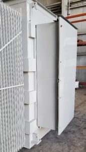

Picture 1: Unit substation style terminal cabinet. Note that the high and low voltage terminal cabinets are on opposite sides and the cabinet has a solid bottom since it does not rest on the concrete pad.
In a pad mount, we always place the terminals in a single cabinet, with a voltage barrier separating them. As you can see in the picture, the bottom is open, which allows the wiring to come up from the concrete pad. These are very typical style transformers that will sit outside of commercial buildings to bring power to the facility. The barrier is solid and keeps the low voltage from the high voltage for safety.
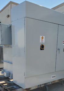
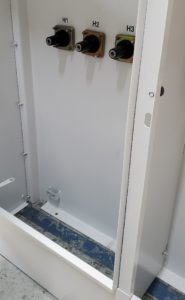
Picture 2: Typical Pad mount transformer. Note that the terminals are all on the same side and in the same cabinet separated by a barrier. Also, note that the floor of the cabinet is open to allow the wiring from the concrete pad to enter the chamber.
Termination Options
Once the transformer type is established, there are several options for termination. One of our most popular is the dead-front bushing for the high voltage side. In terms of configuration, this bushing can be set up in one of two ways: either as a loop feed or a radial feed. A loop feed operates on a branch circuit that loops in another transformer in the circuit. This decision is typically at the request of the end user and utility. In determining our low voltage bushings, we typically consider the required voltage and amperage. The higher the current, the larger the spade terminal will be. These will come with the provision for cable supports to prevent strain on the bushing.
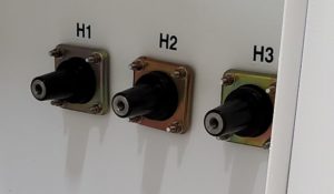
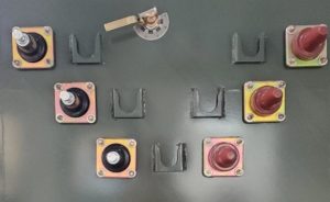
Picture 3: Radial feed and Loop feed dead front bushings
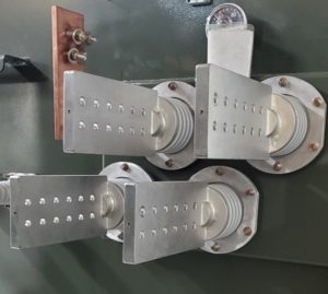
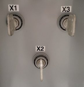
Picture 4: High current spade bushings. Note that one bushing has a 12-hole Nema pattern for KCM cabling, whereas the other has a 4-hole Nema pattern for smaller current.
Voltage Tap Selector Switch Options
The next custom transformer options applies to voltage tap selector switches. Typically, we establish these as a percentage of the nominal incoming voltage from utility or customer-supplied power. These tap switches are usually 5-position or 7-position, depending on how may taps the end user requested. The 5-position tap switch is the most common with tap ranges in ± 2.5% and ±5% voltage increments. When making the change, always de-energize these switches to prevent damage. There are tap switches that can be operated under load, but these are typically used on large power transformers where de-energizing can cause damage to the transformer.
These types of switches are standard on all utility distribution transformers. However, our oil and gas industry frequently utilizes our most popular tap switch. This switch allows the end-user to select up to 25 different voltages for their output either in a delta or wye configuration. The dual switch also allows for different voltage combinations on the transformer.
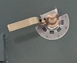
Picture 5: Typical three phase 5 position tap switch. The dual switch is finds application on special outputs with a range of voltages 1100-3800Volts or other combinations of 25 taps.
Custom Transformer Accessories
“Accessories”, which are the last custom transformer option, serve to monitor and protect the transformer during operation. Operating the transformer does not require these devices; however, almost all transformers include many of these devices.
- Pressure relief valve: This device relieves pressure build up during operation. Some of the devices are mechanical in nature, but some are automatic.
- Liquid Level gauge: This device monitors the oil level in the tank. It is critical that the oil doesn’t drop too low as it could cause the transformer to fail in temperature and voltage.
- Liquid Temperature gauge: This device monitors the temperature of the oil and/or coils of the transformers. Temperature is the number one failure mechanism of transformers. If the transformer overheats it can lead to the life expectancy to decrease.
- Pressure vacuum gauge: This monitors the positive and negative pressure in the tank. It assists in determining if there is a leak or other possible issues with the transformer.
- Dissolved Gas Analysis monitor: This device monitors the oil for gasses. Its use is for early detection of potential failure mechanisms.
- Drain valve with sampler and oil valve. Their use is to fill and/or drain oil. The sampler is used to take a small amount of the oil from the transformer for detailed oil analysis that can be used to determine if the oil or transformer has seen any potential damaging issues.
All these devices except the drain valve can come with a contact switch that you can use for controls, such as an alarm for over temperature. To access their controls, the end user wires these into a control box. In some instances, the control box and components may be configured for a hazardous location as shown in the control box below.
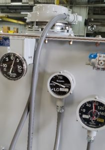
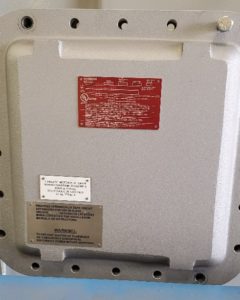
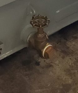
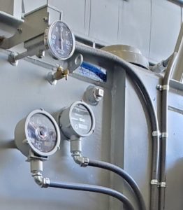
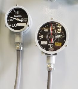
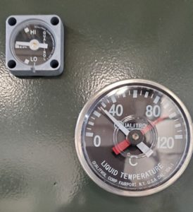
Picture 6: Various accessories that you typically find on oil filled transformers.
Give us a call or email us with any questions you have or to discuss your next custom transformer!
For more information about Transformers, Visit the links below:
How to Determine Transformer Criticality and Things You Need to Know About Transformer Oil
Vissit our YouTube channel for other video content!
