
By Mike Switzer, Product Line Manager
It is important to follow the procedures for electric motor repair. This can help obtain all the needed data/information that will determine if you should proceed with a repair. The following will take you through the most basic processes for Electric Motor Repair.
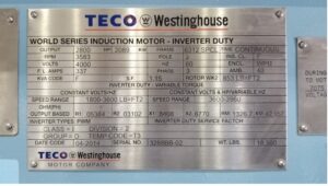
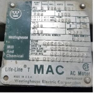
Receiving a Motor for Repair
The first step is to document the nameplate information and take up to four photos from different angles of the motor. This will help to understand the incoming conditions of the motor as received from the customer. The nameplate information is also important when replacing a motor with a new one. Keeping the intended HP, RPM, Voltage, and Frame for the customer is crucial when replacing a motor.
Items to note are: What side is the Terminal Box on in relation to the drive end or opposite drive end? Is the Terminal Box complete? Does it have a rotation tag? Is the motor equipped with space heaters, bearing or stator RTD’s? How about an auxiliary box? Is the motor a ball bearing or sleeve bearing unit? Is it Horizontal or Vertical in application? There are many more items to consider noting during the receiving process.
Disassembly
If a customer requests that the motor be energized and tested for rotation, make sure the rotor spins by hand prior to testing. It is also recommended that a megohmmeter test be performed to ensure the windings are not shorted to ground. If the rotor does not spin, the next procedure is to start the disassembly process.
All motors should be marked in some fashion to indicate which side is the drive end and non-drive end. End frames should be marked in a way that another mechanic will know how to reassemble it back to the way it was received. Hence, the importance of incoming photos. Fan covers are also marked before detaching.
Electrical and Mechanical Testing
The stator portion should be cleaned and baked prior to any electrical testing. The other components can be cleaned as well for mechanical measurements.
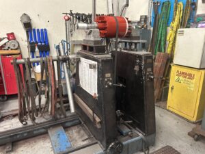
Whether a 3-phase motor is wound with a random or form-style winding, electrical testing is a must to check the integrity of the insulation of the winding. This testing can be performed with a Surge test, P.I. (Polarization Index), and Step Voltage/Hi Pot. These tests will determine whether a recondition of the windings is in order or a rewind is required.
Once the rotor is extracted from the stator core, mechanical measurements can be taken on the shaft to check for the manufacturer’s tolerance as well as end frame housing/seal fits. It is common to follow the ISO 286-2 tolerance using a J6 level. In some countries, a K6 level is used for inspecting the proper clearance of interference fit. Repairs can be made by welding or metalizing to build up the tolerance back to acceptable levels. The same can be said for the end frames of a 3-phase motor.
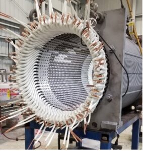
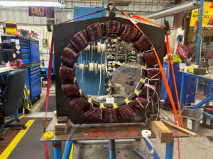
Rewinding
When it comes time to rewind a 3-phase motor, the stator core is placed in a burnout oven to remove the existing varnish from the copper and throughout the slot sections. This allows for easier removal of the coils than if they were in a varnished state. Winding data and connection data will be taken and documented. Documentation is for manufacturing new coils to match the manufacturer’s data to be inserted.
Once the stator core is completely wound, it will go through a varnish system. In reference to random-wound motors, the varnish procedure may include dipping in a vat of Class F rated epoxy varnish. The random winding can also be placed in a VPI system. The insulation used in the slot cells and wedges can be impregnated. The open coils/wire in the slots will not impregnate like a form coil will. A form winding will go through a VPI (Vacuum Pressure Impregnation). The Class rating of the varnish can be Class F or Class H varnish. The stator will then be placed in a bake oven not to exceed 270°F and allow the varnish to set up and cure.
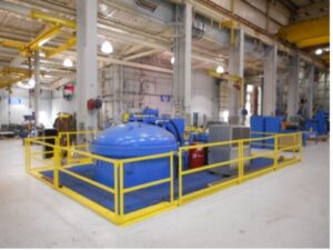
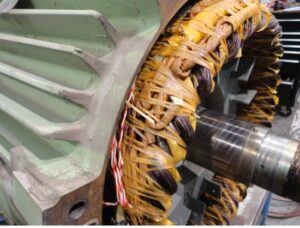
Balancing
Balancing a rotor should be common practice during all types of motor repair. The balance tolerance should be within a G 2.5 or G 1 Balance Grade. Residual unbalance should also be noted to ensure that the tolerance level is within the ISO 1940-1 guidelines. Residual unbalance may need to be considered when applying the API 541 Standards for Petroleum refinery specifications.
Assembly & Testing
The final steps involve assembling the motor as found. Notating the incoming documentation and how the end frames were marked upon disassembly will ensure that the drive end of the shaft and terminal box are correct.
The motor is placed on a machined steel bed that is level and flat. Electrical power is connected to the motor leads. The testing procedure confirms that the motor is running properly at full nameplate voltage and that there are no mechanical or vibration issues. After a successful test, the motor is placed in a paint booth for painting and is ready to be shipped to the customer.
In summary, following the manufacturer’s requirements for mechanical and electrical tolerances can and will extend the life of your 3-phase electric motor. Southwest Electric Co. takes pride in servicing your electric motor, aiming for your satisfaction to increase your bottom line.
To learn about how Southwest Electric Co can help with your motor needs visit: https://www.swelectric.com/industrial-motors/
To learn more about motors on our Youtube channel!
What is the Difference Between a Form Coil and a Mush? (youtube.com)
What is the VPI Process in a 3-Phase Motor? (youtube.com)
What are the Types of Brushes in a DC Motor? (youtube.com)
6 Common Failures in a DC Motor (youtube.com)