
By Ray Urbanic, P.E., VP of Engineering
An arc flash event poses tremendous risk toward safety of personnel, damage of property, and extended loss of productivity. Agencies like NFPA and OSHA have instituted means to identify, calculate, and raise awareness of these risks to personnel, but quite often the means to reduce these risks remain unaddressed. More often than not, facilities end up conceding to live with critical electrical distribution equipment labeled with high or even “dangerous” incident energy levels, subjecting themselves to diminished ability to maintain such equipment while exposing their personnel, property, and productivity to potentially significant loss, should an arc event occur.
This article highlights arc flash mitigation strategies and methods that help reduce the potential arc flash energy levels, and thereby reduce the amount of PPE and long-term infrastructure investment, as well as reduce further risk to loss of production time. These arc flash energy reduction strategies and methods may require one-time investments in equipment modifications, but yield a multitude of benefits year-over-year.
When Less 480 V Fault Current Could Pose Greater Danger
The IEEE 1584 equations for calculating incident energy levels for a given piece of equipment are based primarily upon:
- The system voltage of the equipment
- The available arcing fault current
- The time it takes to clear the arcing fault
Based upon these IEEE equations, the resulting Incident Energy values end up being directly proportional to the square of the available Arc current and the time it takes to clear the Arc fault.
Arcing current is always less than the available 3-phase bolted fault current, due to the impedance of the current traveling through air, versus traveling through a metal conductor like copper. The lower the system voltage, the more pronounced this difference becomes, as the chart below illustrates2:
Most overcurrent protection is designed to interrupt worst-case bolted-fault conditions as quickly as possible. According to the IEEE 1584 chart, typical medium-voltage applications show the following relationship between Arc Fault current and Bolted Fault current:
Iarc = 95-98% of Ibolt
But for low-voltage applications (480V), the relationship changes dramatically:
Iarc = 45-50% of Ibolt
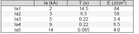
Many overcurrent protective devices are designed to interrupt based upon an inverse Time-Current curve (TCC). In most cases, the higher the current, the quicker the clearing time, and vice-versa. You can observe this in the following example:
A 480 volt, 100 amp fuse with inverse TCC yields the following
Max Fault Current = Ibolt = 20kA → Clearing Time = Tclear = 0.02 sec
However, in the case of an Arcing fault in the same 480V equipment with the same 100 amp fuse:
Iarc = 50% Ibolt
Iarc = 10kA → Tclear = 2.90 sec
The resulting Incident Energy value for the Arcing fault would be substantially higher than for the Bolted fault, given the prolonged duration the arcing current can exist. The higher energy would require more stringent safety precautions for employees, more potentially extensive damage to equipment, and likely longer overall downtime.
As a result, the majority of substations where a primary fuse is protecting the transformer feeding 480V equipment tend to have the highest Incident Energy levels calculated in a facility, at their 480V Main buses. Fortunately, there are methods for reducing this incident energy and the subsequent risks associated.
What’s the Best Arc Flash Mitigation Strategy?
Advancements in arc-detection technology and arc-resistant equipment development have provided new solutions for mitigating arc flash risk to personnel, property, and production. However, each has pros and cons:
Decrease Employee Risk through Arc-Resistant Equipment Design
Pros:
- Redirects arc blast away from the perimeter of gear should an arc event occur, provided all of the manufacturer’s requirements for proper sealing of the entire lineup of arc-resistant equipment are adhered to fully
- Limits required PPE of users around equipment
Cons:
- Proper sealing of the entire lineup is required for arc-resistant benefits to take effect – if one bolt or wireway cover is not properly secured, the integrity of the arc-resistant system becomes compromised.
- The vast majority of arc flash events occur when personnel are exposed to energized parts (open panels, etc). Arc-resistant only protects when it remains sealed – once open, the arc protection is nullified.
- The arc-resistant design itself does not reduce the overall clearing time or resulting incident energy levels, subjecting the interior of the switchgear to the full arc blast, and subsequent damage to be replaced.
- The cost and leadtimes of arc-resistant switchgear tend to be notably higher than standard, non-arc-resistant equipment, typically resulting in longer downtime.
- The design constraints of arc-resistant design tend to limit the ability to configure replacement lineups to match existing conduit locations.
Decreasing Clearing Times (80-300ms range, depending upon coordination)
These methods include:
- Replacing power fuses with selectable (faster) breakers with trip units
- Upgrading electromechanical relays with faster and more selectable microprocessor relays
- Implementing “maintenance mode” or override feature on select relays
- Implementing “arc detection” feature on select relays
Pros:
- Reducing clearing time and incident energy levels also reduces required PPE for users, allowing for proper maintenance of the equipment
- Reducing overall incident energy limits resulting damage, reducing downtime and replacement cost
- Allows for retrofitting of existing equipment and preservation of existing infrastructure (building, conduit, etc)
Cons:
- Can still allow incident energy and resulting damage to occur, requiring personnel to adhere to all NFPA 70E and NESC requirements around equipment
- Not as widely known by personnel – requires proper engineering application to utilize appropriately without compromising downstream coordination
Decrease Clearing Time through Short Circuit Inducement (40-300ms range, depending upon coordination)
This arc flash mitigation approach utilizes the latest technology offered by manufacturers to quickly detect and clear Arc faults by intentionally creating a 3-phase bolted fault within the faulted equipment.
Pros:
- Can offer the fastest arc fault clearing times available on the market , which can further limit the resulting damage
Cons:
- Most designs are not compatible with older equipment, necessitating full replacement and re-routing of existing cable systems
- Newer technology is typically higher cost, longer leadtimes, and only good for one-time operation
- Self-induced faults can place tremendous stresses on the equipment both upstream and downstream, especially on transformer and rotating machine windings
Southwest Electric has extensive experience in analyzing electrical systems and arc flash assessment results, offering custom, engineered solutions for reducing arc flash risk while preserving as much existing equipment and infrastructure possible, maximizing investment effectiveness while minimizing downtime. We will be happy to discuss your custom arc flash mitigation solution with you.
Give us a call, email, or request a quote using the button below to get in touch with us today.
Footnotes:
1 – Electrical Safety Foundation International, “Electrical Safety: Then and Now,” Figure 2 data
2 – Downloaded PDF, “Common Sources of Arc Flash Hazard in Industrial Power Systems In IEC Plants”